
| Minimum Total Energy (GeV) | 2.5 | 5 | 10 |
|---|---|---|---|
| Maximum Total Energy (GeV) | 5 | 10 | 20 |
| Cells | 52 | 64 | 84 |
| Short drift (m) | 0.5 | 0.5 | 0.5 |
| Long drift (m) | 2.0 | 2.0 | 2.0 |
| D angle (mrad) | 156.4442206142160 | 134.6062650623434 | 104.6686081591161 |
| D length (m) | 0.5958624007498240 | 0.7472149648887136 | 0.9253951702451095 |
| D displacement (mm) | 30.19651030200021 | 24.66640953767451 | 20.72963873834226 |
| D dipole (T) | 2.997813333585663 | 4.191313218599995 | 5.289153187390601 |
| D gradient (T/m) | -12.56336682952998 | -19.13765556626068 | -29.03074550693176 |
| D aperture radius (mm) | 131.8774731795656 | 98.33278241799703 | 75.08345310239752 |
| D aperture field (T) | 4.654638405692046 | 6.073172139387677 | 7.468881806187950 |
| F angle (mrad) | -35.61373393768555 | -36.43149463766231 | -29.86878307364487 |
| F length (m) | 0.9514300864320404 | 1.198233028254445 | 1.451173111123141 |
| F displacement (mm) | -8.931878344742322 | -6.227979543072953 | -4.970803353204361 |
| F dipole (T) | -0.5312320109312531 | -0.8003561249393034 | -1.061970351096813 |
| F gradient (T/m) | 10.35041414019155 | 15.38155440293255 | 23.69759841076119 |
| F aperture radius (mm) | 207.4326841609991 | 166.0854534894128 | 129.9898743301357 |
| F aperture field (T) | 2.678246198209145 | 3.355008563322430 | 4.142418190437684 |
| RF Cavities | 42 | 46 | 54 |
| Energy Gain per Cavity (MeV) | 12.52984394532481 | 12.39644070260180 | 12.64502711350376 |
| Turns | 4.803021358170473 | 9.012597500995915 | 15.44969574802365 |
| Circumference (m) | 210.4908297248826 | 284.5447937784257 | 409.6672306170535 |
| Time of flight range, per cell (ps) | 18.51244338195651 | 12.58317050455552 | 7.720029576745513 |
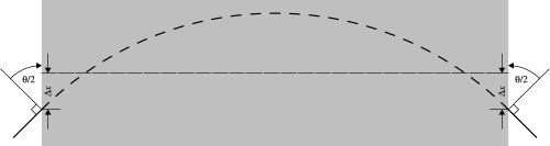
The lattice uses so-called "rectangular bends," where the central axis of the magnet is straight, not curved. The following diagram illustrates the meaning of the angles and displacements for these magnets:
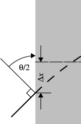
First the coordinate system is rotated by an angle θ/2 (θ is the "angle" above) such that for positive θ, a particle initially with zero angle would now have an angle of θ/2 in the positive x direction. Next, the coordinate system is displaced by an amount -Δx (Δx is the "displacement" above), meaning that a particle initially at x=0 now has x=-Δx. Then one tracks through the magnet in a straight coordinate system, with x=0 being the center of the magnet. The field and gradient given above are on the central axis of the magnet. Next, the coordinate system is displaced by Δx. Finally, the coordinate system is rotated by an angle θ/2. The length of the magnet is the length of the (straight) central axis above, not the arc length of some "reference particle."
J. Scott Berg <jsberg@bnl.gov> 15 September 2005. |
Privacy and Security Notice |